micropython-rp2-rs485-examples
What's this?
This is a small collection of some programs I wrote to test the functionality of some cheap TTL-UART to RS485 converters, written in MicroPython
Here's a short list of the different programs and what they do:
-
rs485_send.py: sends a incrementing counter (starting at 0) as an UTF-8 encoded string with \r\n as delimiter over rs485
-
rs485_receive.py: receives utf-8 encoded strings and prints them out as soon as a \n is received.
-
rs485_pingpong.py: this implements a simple ping-pong over two channels (4 converters needed). For more information, see Wiring.
Prerequisites
To be able to run all the examples successfully, you need two MicroPython-enabled microcontrollers (Raspberry Pi Pico 1 tested) and 4 TTL-UART to RS485 converters, with two of them connected to each μController (see Wiring). Also, both microcontrollers should have MicroPython running on them (at time of writing this the latest tested version was 1.23.0).
If you met all these requirements, let's start wiring the parts together!
Wiring
For the (simple) send and receive programs, theres just to devices with MicroPython (rp2 flavor tested) needed, as well as two TTL-UART to RS485 converters, one connected to each of them. For the ping-pong example, you will need two channels (one for sending and one for receiving) for each MicroPython device. When using WaveShares Pico 2-Channel HAT, no wiring (between converters and microcontroller) is needed at all!
Just wire two MicroPython devices as shown below (obviously connect different converters to the different microcontrollers ;)
| Converter | Pin on converter | Pin on Pi Pico1 |
|---|---|---|
| TTL-UART to RS485 converter 1 | VCC | 3v3 Out |
| TTL-UART to RS485 converter 1 | GND | GND |
| TTL-UART to RS485 converter 1 | DI (driver in) | GP0 (UART0 TX) |
| TTL-UART to RS485 converter 1 | RO (receiver out) | GP1 (UART0 RX) |
| TTL-UART to RS485 converter 1 | DE3 (driver enable) | GP2 (set HIGH/LOW) |
| TTL-UART to RS485 converter 1 | RE3 (receiver enable) | GP2 (set HIGH/LOW) |
| TTL-UART to RS485 converter 22 | VCC | 3v3 Out |
| TTL-UART to RS485 converter 22 | GND | GND |
| TTL-UART to RS485 converter 22 | DI (driver in) | GP4 (UART1 TX) |
| TTL-UART to RS485 converter 22 | RO (receiver out) | GP5 (UART1 RX) |
| TTL-UART to RS485 converter 22 | DE3 (driver enable) | GP3 (set HIGH/LOW) |
| TTL-UART to RS485 converter 22 | RE3 (receiver enable) | GP3 (set HIGH/LOW) |
[1] as I used the Pico, adjust for your favourite microcontroller (but don't forget also changing the pinout in the programs as well1)
[2] only needed for the ping pong example
[3] as the driver/receiver enable pins respond at opposite logic levels (receive enable turns on receiver output when LOW, while driver enable enables driver output when set HIGH), they can be shortened together and be controlled by only one pin on our microcontroller
Then, connecting the A+, B- and GND wires of the respective converters together (converter 1 of μC1 to converter 1 of μC2, converter 2 of μC1 to converter 2 of μC2), you've just created a simple RS485 bus! Now upload the scripts to both microcontrollers and try what you want to try!
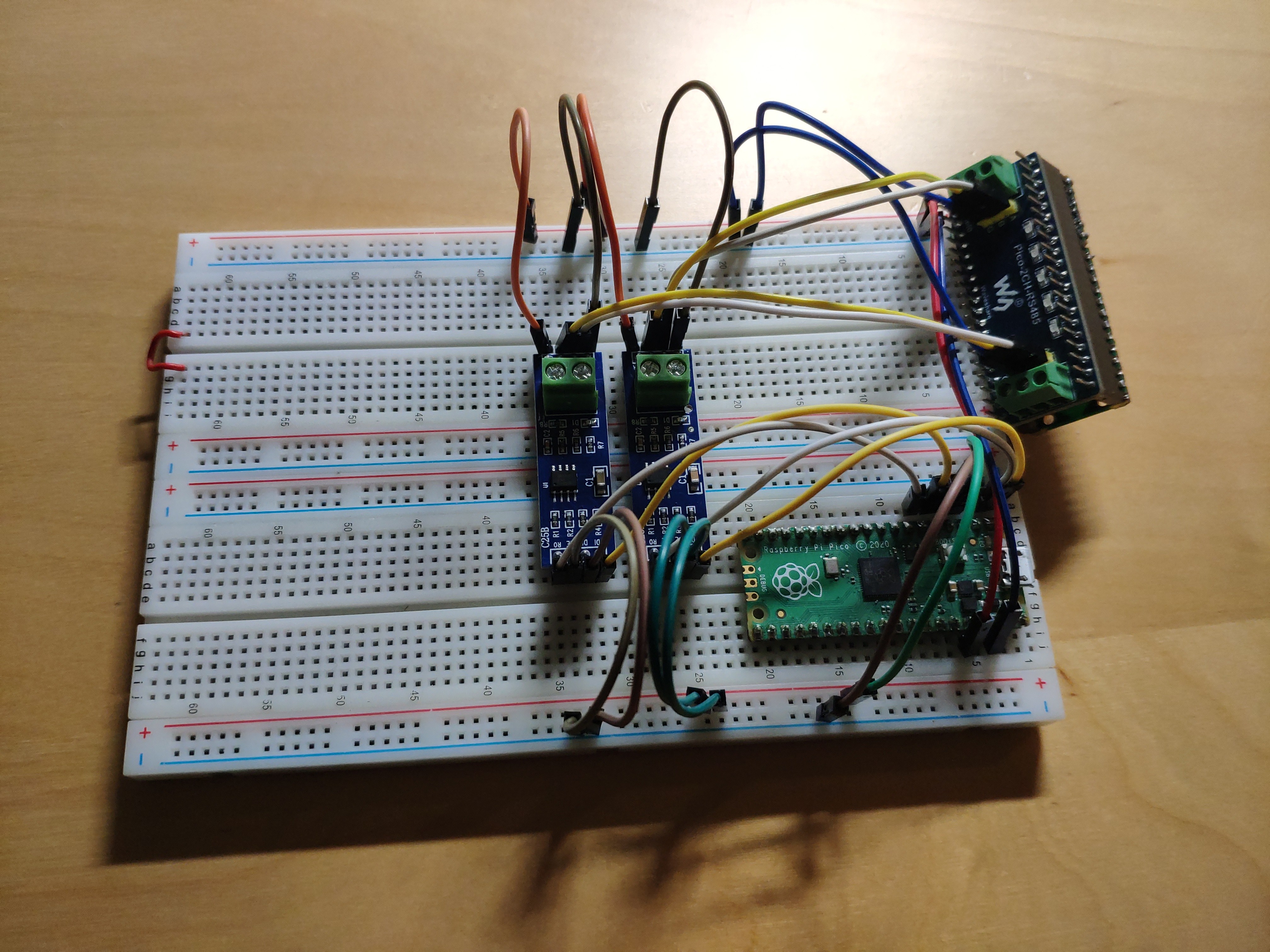
Example wiring on a breadboard, one Pico backed with WaveShares HAT, the other one connected to two MAX485 breakout boards:
Useful links
- https://www.berrybase.de/2-kanal-rs485-modul-fuer-raspberry-pi-pico-sp3485-transceiver - Pinout for a two-channel rs485 converter HAT by waveshare for the pi pico I used during development
- https://www.analog.com/media/en/technical-documentation/data-sheets/MAX1487-MAX491.pdf - Datasheet of MAX485, a well-known chip soldered on another converter I bought (gives useful insights in how the UART communications work, and how to enable/disable read/write)
- https://www.python-forum.de/viewtopic.php?t=56795 - German forum entry with sample code
- https://www.waveshare.com/wiki/Pico-2CH-RS485 - the wiki entry of waveshare about the 2-Channel converter I used among other converters (also contains sample code)
- https://docs.micropython.org/en/latest/library/machine.UART.html - Documentation of the UART library of MicroPython I used for transferring data to the converters
License
see LICENSE.md
